Translate

Thursday, 15 August 2019

Fleming’s Left Hand Rule and Fleming’s Right Hand Rule

Whenever a current carrying conductor comes under a magnetic field, there will be a force acting on the conductor. The direction of this force can be found using Fleming’s Left HandRule (also known as ‘Flemings left-hand rule for motors’).
Similarly if a conductor is forcefully brought under a magnetic field, there will be an induced current in that conductor. The direction of this force can be found using Fleming’s Right Hand Rule.
In both Fleming’s left and right hand rules, there is a relation between the magnetic field, the current and force. This relation is directionally determined by Fleming’s Left Hand rule and Fleming’s Right Hand rule respectively.
These rules do not determine the magnitude but instead show the direction of any of the three parameters (magnetic field, current, force) when the direction of the other two parameters is known.
Fleming’s Left-Hand rule is mainly applicable to electric motors and Fleming’s Right-Hand rule is mainly applicable to electric generators.

Fleming’s Left Hand Rule

It is found that whenever a current carrying conductor is placed inside a magnetic field, a force acts on the conductor, in a direction perpendicular to both the directions of the current and the magnetic field.
Fleming's Left Hand Rule
In the figure below, a portion of a conductor of length ‘L’ is placed vertically in a uniform horizontal magnetic field of strength ‘H’, produced by two magnetic poles N and S. If the current ‘I’ is flowing through this conductor, the magnitude of the force acting on the conductor is:

Left Hand Rule Magnetic Field
Hold out your left hand with the forefinger, second finger and thumb at the right angle to one another. If the forefinger represents the direction of the field and the second finger represents that of the current, then thumb gives the direction of the force.
While current flows through a conductor, one magnetic field is induced around it. The magnetic field can be imagined by considering numbers of closed magnetic lines of force around the conductor. The direction of magnetic lines of force can be determined by Maxwell’s corkscrew rule or right-hand grip rule. As per these rules, the direction of the magnetic lines of force (or flux lines) is clockwise if the current is flowing away from the viewer, that is if the direction of current through the conductor is inward from the reference plane as shown in the figure.
Rule Hand Rule Magnetic Field

Now if a horizontal magnetic field is applied externally to the conductor, these two magnetic fields i.e. field around the conductor due to the current through it and the externally applied field will interact with each other. We observe in the picture that the magnetic lines of force of external magnetic field are from N to S pole that is from left to right.
The magnetic lines of force of external magnetic field and magnetic lines of force due to the current in the conductor are in the same direction above the conductor, and they are in the opposite direction below the conductor. Hence there will be larger numbers of co-directional magnetic lines of force above the conductor than that of below the conductor.
Consequently, there will be a larger concentration of magnetic lines of force in a small space above the conductor. As magnetic lines of force are no longer straight lines, they are under tension like stretched rubber bands.
Rule Hand Rule Magnetic Force
As a result, there will be a force which will tend to move the conductor from the more concentrated magnetic field to less concentrated magnetic field, that is from the present position to downwards. Now if you observe the direction of the current, force and magnetic field in the above explanation, you will find that the directions are according to the Fleming left-hand rule.
Fleming Right Hand Rule
As per Faraday’s law of electromagnetic induction, whenever a conductor moves inside a magnetic field, there will be an induced current in it. If this conductor gets forcefully moved inside the magnetic field, there will be a relation between the direction of applied force, magnetic field and the current. This relation among these three directions is determined by Fleming’s right-hand Rule.
Fleming’s right hand rule
This rule states “Hold out the right hand with the first finger, second finger and thumb at the right angle to each other. If forefinger represents the direction of the line of force, the thumb points in the direction of motion or applied force, then second finger points in the direction of the induced current”.

Who Invented The Left and Right Hand Thumb Rules?

The left and right hand thumb rules were founded by John Ambrose Fleming in the late 19thcentury.
John discovered both of these rules and named them after himself. The rules are now well known as Fleming’s left and right-hand rule.

Ohm’s Law

Ohm’s law deals with the relationship between current, voltage and ideal resistance. This relationship was introduced by German physicist George Simon Ohm. That is why the law is well known as Ohm’s law.Georg Simon Ohm
Ohm’s law first appeared in the book written by Georg Simon Ohm (German) in 1827.

Ideal Resistance

Before going to actual topic let us know what is an ideal resistance. Ideal resistance is that resistance which possesses the property of pure resistance and also it doesn’t change its resistivity due to change in voltage or current imposed on it.

Statement of Ohm’s law

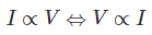
At constant temperature, the current through an ideal resistor is directly proportional to the voltage applied across the resistor.

The constant of proportionality is written as R and this is the resistance value of the resistor.

Ohm’s Law Formula

The relationship between current, voltage and resistance can be written in three different ways. When a known voltage is applied across a known resistance the current through the resistance can be determined by the relationship

When a known current flows through a known resistance the voltage appeared across the resistance can be determined by the relationship

When a known voltage is applied across a resistance and the current through the resistance is also known then the value of the reactance can be determined by the relationship
Ohm's Law Triangle

Determining Power from Ohm’s Law

When current flows through a resistance there will be a dissipation of power from the resistance. This power can easily be determined by using Ohm’s law. As we know power is the product of current and voltage. If the current I ampere flows through a resistance and voltage V volts is the voltage across the resistance then power
Using Ohm’s law we can write
From that relationship we can determine power of a resistance if either voltage and resistance or current and resistance are known to us.
From the same relation for a given dissipated power, we can determine the unknown resistance value of either current or voltage is known.
If any two of power, current, voltage and resistance are known then with the help of Ohm’s law we can find out other two variables.

Why the temperature is kept constant in Ohm’s law

The main criteria for Ohm’s law is to keep the resistance constant because proportionality constant in the relationship is resistance R. But we know that the variation of temperature affects the value of resistance so to keep the resistance constant during experiments of Ohm’s law the temperature is considered constant.

Applications of Ohm’s Law

There are thousands of applications of this law in our daily life. We will show only a few of them in this article.
  • Conventional Domestic Fan Regulator is one very common device where the current through the fan gets regulated by controlling the resistance of the regulator circuit.
  • In voltage divider circuit this law is used to divide source voltage across the output resistance.
  • In electronic circuits, there are many purposes where intentional voltage drop is required to supply specific voltage across different electronic elements. This is done by applying Ohm’s law.
  • In mainly dc ammeter and other dc measuring instruments shunt is used to divert current. Here also Ohm’s law is used.
The list will continue as much as you think.

Limitation of Ohm’s Law

The limitations of Ohm’s law are explained as follows:
  1. This law cannot be applied to unilateral networks.
    A unilateral network has unilateral elements like diodetransistors, etc., which do not have same voltage current relation for both directions of current.
  2. Ohm’s law is also not applicable for non – linear elements.
    Non-linear elements are those which do not have current exactly proportional to the applied voltage, that means the resistance value of those elements changes for different values of voltage and current. Examples of non – linear elements are thyristorelectric arc, etc.

Monday, 12 August 2019

IEC 61850 Standard

IEC 61850 is the global standard for communication in substations. It enables integration of all protection, control, measurement and monitoring functions within a substation, and additionally provides the means for high-speed substation protection applications, interlocking and intertripping.
The comprehensive implementation facilitates integration of the relays into IEC 61850-based Substation Automation Systems and at the same time it allows the interface with different vendors’ Merging Units over the IEC 61850 Process Bus.
It combines the convenience of Ethernet with the performance and security which is essential in substations today. IEC 61850-enabled relays are fitted with an integral Ethernet card providing both copper and fiber Ethernet.
No external adaptors or data concentrators are necessary and only standard Ethernet equipment such as switches and substation grade switches etc are required.

Peer-to-Peer Message (GOOSE)

Generic Object-Oriented Substation Event (GOOSE) messages can be used for interlocking, disturbance recording cross-triggering, breaker failure protection tripping, directional comparison bus protection and many other advanced applications, thus eliminating extensive hardwiring in equipment bays and so reducing the cost of implementing advanced distributed protection and control schemes.

Process Bus Interface

Analog interface units (or Merging Units) located in the substation yard interface with conventional or non-conventional instrument transformers and send the sampled current and voltage values over fiber, thus significantly reducing (actually eliminating) the copper wires between the substation primary equipment and the protection, control and measuring devices.

True Interoperability

One protocol is all that is needed in the substation. Costly gateways and split path communications are thus avoided. Peer-to-peer messages, control commands, disturbance files transfer or event driven reports are interleaved on a single Substation Bus network.
Multiple clients can be integrated, allowing authorized operators and engineers to interrogate and control the substation IEDs.
The Substation Configuration Language defined in the standard represents a leap in the engineering process related. The self-descriptive nature of IEC 61850-compatible IEDs means that system integration and commissioning are easier. Standardized data classes and services mean IEC 61850-enabled IEDs can operate seamlessly in multi-vendor environments

SF6 or vacuum?

Approximately 35 years ago, in the mid 1960s, two new breaker technologies, one using SF6 gas and the other vacuum as its arc quenching medium, were introduced to the market.
Research and development work on both technologies has continued unabated since then, and today it can be said that, together, they have all but replaced the older types of switchgear.
Instead of an objective selection based on real-world characteristics, the choice is very much driven by the circuit-breaker manufacturer.
SF6 and vacuum switchgear enjoy varying market success in the different parts of the world whereas Europe and most of the Middle East countries tend to favor SF6, China, Japan and the USA definitely prefer vacuum. In other regions, the two technologies are equally popular.
Bulk-oil and minimum-oil technologies are still used in China, Eastern Europe, India and Latin America, but trends clearly indicate that these technologies will disappear very soon, to be replaced by SF6 and vacuum.
ABB concentrates today almost entirely on the two dominant technologies, and is equally present in the market with both SF6 and vacuum.
Experience with more than 300,000 MV circuit-breakers of both designs installed worldwide, backed up by over 30 years of intensive involvement in research [1], has convinced ABB that the two technologies are entirely complementary, though in some cases their different designs can be seen as alternatives.
Based on this conviction that SF6 and vacuum have equally important roles to play, the company has continued to force the development of both, and hence, as the world’s largest manufacturer of MV circuit-breakers, occupies the unique position of being able to provide unprejudiced advice and assistance in the selection of switchgear for any special application.
x

Monday, 27 May 2019

MAKING CAPACITY OF CIRCUIT BREAKER

Circuit breaker is required to perform the following three duties:

1. It must be capable of opening the faulty circuit and breaking the fault current.
2. It must be capable of being closed on to a fault.
3.  Must be capable of carrying fault current for a short time while another breaker is clearing the fault. 

Depending on the above duties circuit breaker has three ratings breaking capacity, making capacity and short time capacity.

MAKING CAPACITY

The capacity of a breaker to make current depends upon its ability to withstand and close successfully against the effects of electromagnetic forces. These forces are proportional to the square of maximum instantaneous current on closing. So making capacity is stated in terms of a peak value of current. The peak value of current during the first cycle of current wave after the closure of circuit breaker is known as making capacity. To find making capacity multiply symmetrical breaking current by root 2 to convert from r.m.s to peak and then by 1.8 to include the doubling effect of maximum asymmetry. Making capacity = 2.55 * symmetrical breaking capacity.

SHORT TIME RATING OF CIRCUIT BREAKER

Circuit breaker is required to perform the following three duties:

1. It must be capable of opening the faulty circuit and breaking the fault current.
2. It must be capable of being closed on to a fault.
3.  Must be capable of carrying fault current for a short time while another breaker is clearing the fault. 

Depending on the above duties circuit breaker has three ratings breaking capacity, making capacity and short time capacity.

SHORT TIME RATING

It is the period for which the circuit breaker is able to carry fault current while remaining closed. The fault on the system of very temporary nature persist for 1 or 2 sec after which the fault will be cleared, so the breaker should not be tripped in such situations. This means the circuit breakers should be able to carry high current safely for some specified period while remaining closed. i.e they should have short time rating. It depends on its ability to withstand electromagnetic force effects and temperature rise.

BREAKING CAPACITY OF CIRCUIT BREAKER

Circuit breaker is required to perform the following three duties:

1. It must be capable of opening the faulty circuit and breaking the fault current.
2. It must be capable of being closed on to a fault.
3.  Must be capable of carrying fault current for a short time while another breaker is clearing the fault. 

Depending on the above duties circuit breaker has three ratings breaking capacity, making capacity and short time capacity.

 BREAKING CAPACITY

It is current that a circuit breaker is capable of breaking at a given recovery voltage under specified conditions. The breaking capacity is always stated at the r.m.s value of fault current at the instant of contact separation. When a fault occurs there is considerable asymmetry in the fault current due to presence of d.c component. The d.c component dies away rapidly.

Breaking capacity is expressed in MVA by taking into account the rated breaking current and rated service voltage. Thus if I is the rated breaking current in amperes and V is rated service line voltage in volts, then for a three phase circuit breaking capacity = √ 3 * V * I * 10 –6 MVA.